High-Power DC/DC Converter
Development of a 28 kW DC/DC converter with an efficiency of more than 98%
In reply to a customer inquiry, we developed a demonstrator of a 28 kW DC/DC converter within only 6 months in 2017:
Technische Daten:
| Topology | Multiphase Buck |
| Input voltage | 65..100 V |
| Output voltage | 20..60 V |
| Output current | 0..480 A |
| Switching frequency | 200 kHz |
| Efficiency | Up to 98.5% |
| Installation space | Two 19″ subracks, 3 RU |
| Control logic | FPGA/Microcontroller |
| Controller | Cascade controller current/voltage |
| Current controller | Analogue |
| Voltage controller | Digital |
| Interfaces | CAN/CANopen USB |
The focus of the customer was not on high efficiency but on a construction which was as inexpensive as possible. However, in this performance category mechanical construction and cooling are a cost factor which should not be neglected. It might therefore make sense to realise the converter itself as small and as light as possible and with a high efficiency, but on the other hand somewhat more expensive. The money invested here can then be saved again with the mechanical construction, cooling and energy costs.
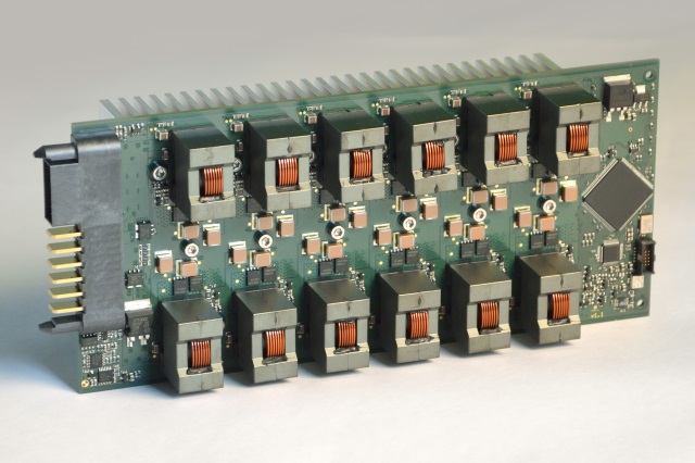
or this reason an approach was used with which all power semiconductors are soldered directly onto PCBs as SMD components.
On the basis of previous experience, a platform consisting of single phases with a rated output of 400 W was developed. Twelve phases per PCB enable outputs of up to 4.8 kW per PCB and power module (19″ size: 3 RU/14 HP). This corresponds to a power density of about
4 kW per litre.
The 12 phases are operated in an interleaved manner, meaning that the PWM cycles are controlled with a time delay so as to cancel the ripple current as efficiently as possible. The advantage of the relatively small phases is that they can be constructed in a very compact manner and therefore with low magnetic leakage. This enables very steep switching edges and thus high switching frequencies. With high switching frequencies relatively small inductive components can be used, which are available at low cost in large quantities. Due to the 12-phase interleaving the base clock is, from the point of view of EMC, multiplied by a factor of 12 and its amplitude is considerably reduced. This means that the first significant emission per power module is, as regards EMC, 2.4 MHz. EMC filters can thus, despite the high output, be designed to be very small and inexpensive.
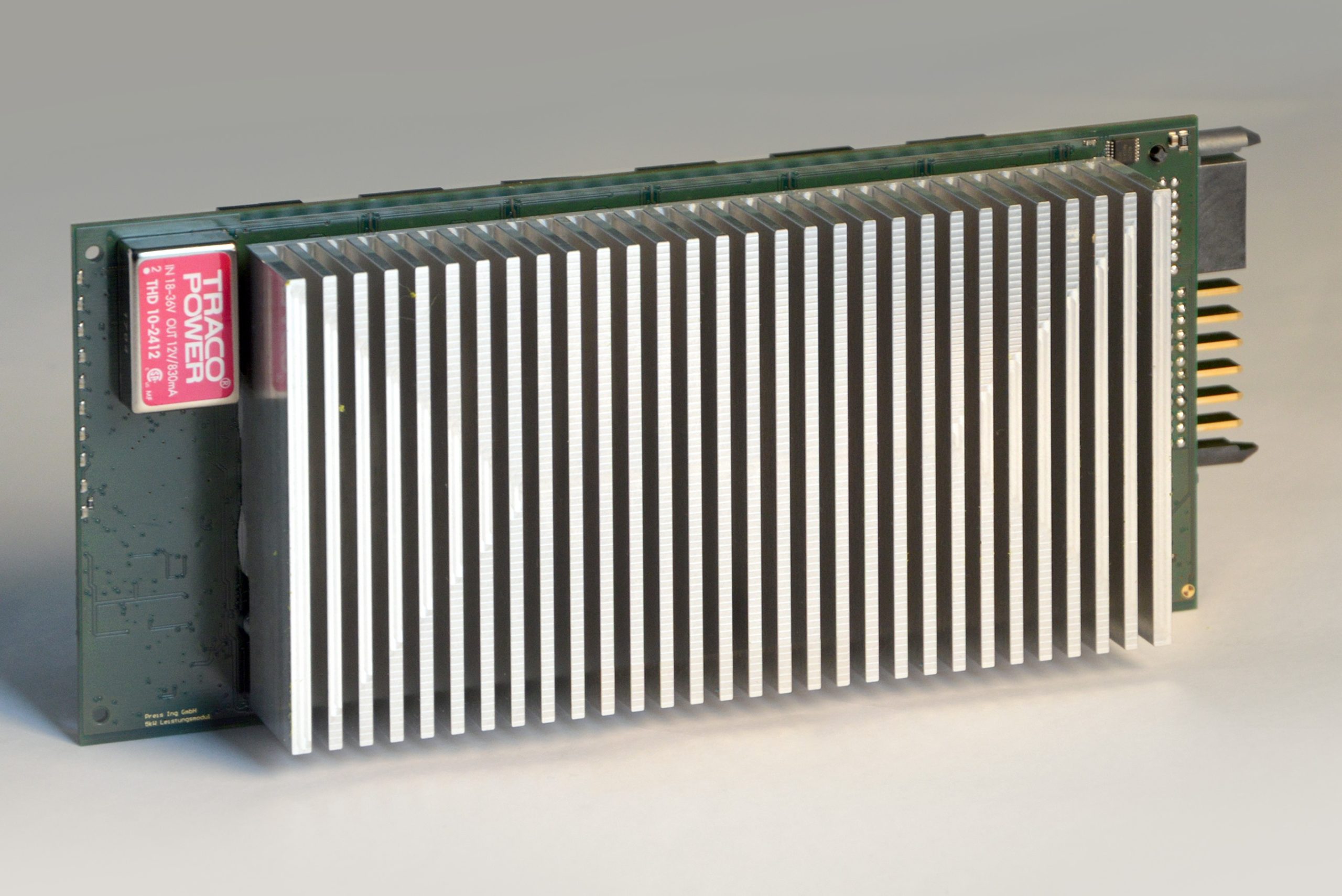
50% of the rated load could already be realised in laboratory operation without a heat sink and air flow. For cooling at full load, a heat sink was screwed directly onto the back of the PCB and fastened with a heat conduction pad. Cooling takes place exclusively exclusively through PCB vias, which is completely sufficient in view of the low power loss per transistor. For this reason special expensive PCB technology is unnecessary.
A small FPGA drives the interleaved 12 phases and reads the analogue value of the discretely constructed current controller with an ADC.
Due to the parallel connection of six 4.8 kW modules in one 3 RU 19″ subrack the peak output of 28.8 kW is attained: the efficiency is still above 97%. An only half-full second 19″ subrack houses the higher-level control module, which performs voltage control, monitoring and the interfaces with the outside world via an STM32 microcontroller. The energy self-supply and several other peripheral components are also located inside this subrack.

To visualise the performance data for the specific customer application a Windows 10 tablet was used, whose LabVIEW front end is supplied with data through the DC/DC microcontroller via a USB connection.
For possible series development there exists among other things the following optimization potential:
- Single phases with higher power output (1..2 kW) so as to decrease the costs of single-phase drive (gate driver, FPGA, monitoring . . .)
- Fully digital control for more flexible parameterization
- Optimisation of switching frequency -> trade-off between power density and efficiency
- Optimisation of installation space by downsizing the overdimensioned cooler and realising the whole of the device in only one 19″ subrack.
The use of this demonstrator successfully showed the advantages which a high-channel multiphase DC/DC converter can offer at high outputs.