The AF10 is not simply a slimmed-down function generator. The applications of both unit categories are significantly different. What can the AF10 do which a function generator cannot?
- Low-resistance output
- Load current up to 1 A
- Output voltage up to 24 V
- Output power up to 24 W
- Push-pull/open drain function
- Very simple operating concept reduced to the PWM function
- Control of up to six external gate drivers with adjustable timing, enabling control of almost any number of output stages
- Simple, PLC-compatible interfaces for remote control
- . . .
Also in our company, the AF10 is one of the laboratory units most in demand and is used for many purposes. Occasionally one can even speak of “abuse”.
Some application examples from practice:
Design of the control loop of DC/DC converters
A proven practical approach for safeguarding the stability reserve of switching regulators is to measure and evaluate their response to a load step or an input voltage step.
The open drain function of the AF10 can be used for load steps. With this function an additional load can be cyclically added on with a suitable load resistance.

The figure shows a load step on the 3.3 V voltage rail and its effects on all other voltage rails of an assembly.
To investigate input voltage steps the AF10 can be connected in series to a laboratory power supply unit. In this way, very steep steps up to 24 V can be realized in Push/Pull operation.
The advantage of this approach compared with the simpler approach using a switch is, among other things, reproducibility, as contact bounce does not occur.
Testing overvoltage protection
We develop automotive electronics whose behaviour towards short input voltage transients up to 60 V and more must be tested. We mainly use the AF10 to test in our laboratory the functioning of the circuitry which we have developed. For the test, the AF10 is connected in series to a laboratory power supply unit and generates short overvoltages up to 24 V. If the 24 V are insufficient, or if more power is required, we use the external half-bridge module with which pulses with an amplitude up to 60 V can be generated.
Testing undervoltage behaviour
As with the overvoltage test, the AF10 can also be used for undervoltage tests. Also for these tests a laboratory power supply unit is connected in series, and the voltage level and the duration of the undervoltage are set using the appropriate configuration of the AF10.
Measuring inductances

An RLC meter can measure inductance and other parameters of a coil. However, if one is more interested in saturation behaviour and other non-linear effects, measuring in the time range with the AF10 and an oscilloscope may be very informative.
In the example, an inductance was connected direct at the output of the AF10. With a frequency of 15 Hz, a duty cycle of 0.1% and an output voltage of 10 V the following image was recorded with the oscilloscope.
From this the following characteristics of the inductance can be determined:
- At 10 V, the current first increases by approx. 40 mA per 20 µs.
The inductance is therefore about 5 mH. - The saturation current is approx. 100 mA.
- By applying an appropriate tangent, the inductance can be determined for every DC value.
In the example, with 100 mA:
200 mA/44 µs at 10 V => 2.2 mH
In this context, several other measuring scenarios are conceivable, for example for determining remanence.
High-speed camera substitute
One can purchase an expensive high-speed camera to visualize the very fast periodic movement of a diaphragm valve. The other, more creative way is to construct a stroboscope from the AF10 and a high-power LED and to observe the opening and closing of the valve in slow motion using suitable frequency and duty cycle settings.
This can also be filmed with the correct settings of a digital camera (exposure time).
The video was made with a customary digital camera. The noise of the valve can be heard, which opens and closes several thousand times in the course of the video. By flashing with the stroboscope with a suitable frequency, a single opening/closing cycle can be viewed in slow motion.
Missing laboratory power supply?
Occasionally the two laboratory power supply units at the workplace are not sufficient. An auxiliary power supply of, for example, 5 V is required.
The AF10 helps out quickly and easily if it is not being used for another purpose.
With a duty cycle of 100 % the AF10 can be used very easily as an additional voltage source with an ampacity of up to 1 A.
Optimization of timing of half-bridges and full bridges
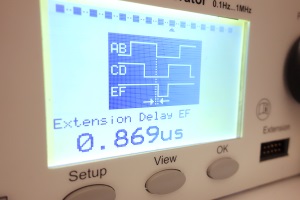
The extension socket of the AF10 makes it possible to control external power modules such as half-bridges and full bridges. The control scheme of a phase-shifted full bridge for forward converters has also been realized.
If the power module with the gate drivers has already been realized, it is very easy to optimize the switch timing with the AF10. The effects of, for example, additional dead time can be very simply and effectively determined and evaluated.
Test / endurance tests
The most important application of the AF10 with our customers is certainly the area of tests and endurance tests. The PWM generator is suitable for testing all electronics with a PWM interface, which is still in widespread use in automotive construction. In combination with the programmable ramp generator an arbitrary number of PWM traces can be realized, which can then be repeated for several months.
For control units with a high-resistance pull-up/open drain input the AF10 is particularly suitable if used with the 8-channel PWM extension available as an option. This offers eight open drain outputs on the back of the unit, with which eight DUTs (devices under test) can be simultaneously controlled.
However, also DC motors and other actuators controlled by PWM can be directly tested with the AF10. If the internal half-bridge with the 1 A output is not sufficient, also larger actuators can be operated with the external power modules available as an option.
With the H-bridge which will be available soon, also motors for example can then be rotated forwards and backwards (duty cycle from -100 % to +100 %), which can be very helpful for a wear test.
There is no limit to the use of devices controlled with PWM. Here is a speculative list of possible DUTs:
- Pumps
- Fans
- Electrical actuators
- Electromagnets
- Magnetic valves
- Solenoids
- DC-Motors
- . . .