Project examples
Here you will find some project examples that demonstrate our working methods and our range of experience.
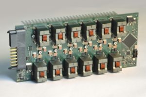
High-Power DC/DC Converter
Development of a 28 kW DC/DC converter with an efficiency of more than 98%
In reply to a customer inquiry, we developed a demonstrator of a 28 kW DC/DC converter within only 6 months in 2017:

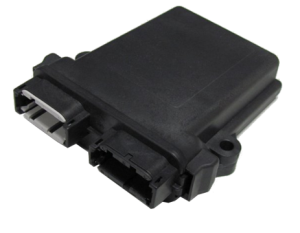
Evil little diode?
Automotive electronics with EMC problems
Electromagnetic suppression of an automotive component. Time and manpower were scarce resources for our customer.
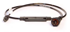
Sensitive to everything that may come along
Sensor system based on LIN bus
Lorem ipsum dolor sit amet, consetetur sadipscing elitr, sed diam nonumy eirmod tempor invidunt ut labore et dolore magna aliquyam erat, sed diam voluptua.
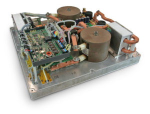
Fuel Cell
DC/DC converter for fuel cell vehicle
Development and production of a customized full functional 21-kW DC/DC converter in only 8 months.

Project management under pressure
Intensive support of an automotive supplier while developing his products towards the series production stage
Lorem ipsum dolor sit amet, consetetur sadipscing elitr, sed diam nonumy eirmod tempor invidunt ut labore et dolore magna aliquyam erat, sed diam voluptua.
“Freshly” arrived
Temperature data loggers for refrigerated transportation
Lorem ipsum dolor sit amet, consetetur sadipscing elitr, sed diam nonumy eirmod tempor invidunt ut labore et dolore magna aliquyam erat, sed diam voluptua.